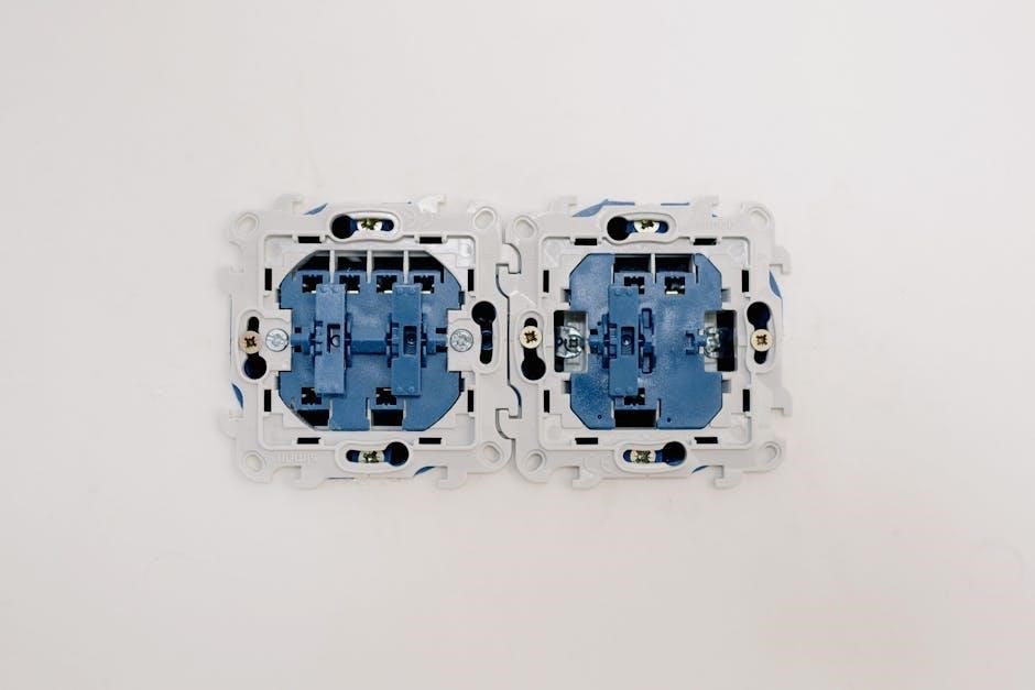
A 2-way switch wiring diagram is a visual guide that explains how to connect switches and wires to control lighting from multiple locations. It simplifies installation by showing the flow of electrical connections‚ ensuring safety and efficiency. Understanding these diagrams is crucial for proper circuit setup and troubleshooting‚ helping you master the fundamentals of electrical wiring systems.

Overview of 2-Way Switches and Their Importance
2-way switches are essential components in electrical systems‚ enabling control of lighting or appliances from two different locations. Their importance lies in their versatility‚ allowing seamless operation of fixtures like ceiling fans or multiple light sources. These switches are widely used in both residential and commercial settings due to their ability to enhance convenience and safety. Designed with three terminals (COM‚ L1‚ and L2)‚ they provide a straightforward yet efficient way to manage electrical circuits. Understanding how to install and wire these switches is crucial for maintaining safety and ensuring reliable performance in any electrical setup.
Why Understanding Wiring Diagrams is Essential
Understanding wiring diagrams is crucial for safely and effectively installing 2-way switches. These diagrams provide a clear visual representation of connections‚ preventing errors during setup. They help identify components like COM‚ L1‚ and L2 terminals‚ ensuring wires are connected correctly. Miswiring can lead to electrical hazards‚ making diagrams indispensable for avoiding such risks. They also simplify troubleshooting‚ guiding users through diagnosing issues efficiently. Whether you’re a professional or a DIY enthusiast‚ a wiring diagram is your roadmap to successful installation‚ saving time and ensuring compliance with safety standards.

Components of a 2-Way Switch
A 2-way switch consists of three terminals: COM (common)‚ L1‚ and L2. These terminals enable the switch to control the flow of electricity in a circuit efficiently.

Terminals in a 2-Way Switch: COM‚ L1‚ and L2
The terminals in a 2-way switch are labeled COM‚ L1‚ and L2. The COM terminal is the common terminal‚ which is always connected to the power source. L1 and L2 are the output terminals‚ controlling the flow of electricity to the light or device. When the switch is toggled‚ the connection between COM and either L1 or L2 changes‚ allowing the circuit to be switched on or off. Proper wiring of these terminals is essential for safe and effective operation of the switch.
Understanding SPDT (Single Pole Double Throw) Switches
A SPDT (Single Pole Double Throw) switch is a fundamental component in 2-way switch wiring. It features three terminals: COM (common)‚ L1‚ and L2. The SPDT switch allows the electrical current to be directed to one of two circuits‚ depending on its position. When the switch is toggled‚ the COM terminal connects to either L1 or L2‚ enabling control of a light or device from two different locations. This configuration is essential for 2-way switching systems‚ providing flexibility and convenience in lighting control. Understanding SPDT switches is crucial for interpreting wiring diagrams and ensuring safe‚ efficient installations in both residential and commercial settings.

The 2-Way Switch Wiring Diagram Explained
The 2-way switch wiring diagram visually represents the circuit‚ showing how live and neutral wires connect through the switch to control lighting efficiently and safely.
Visual Representation of the Wiring System
The wiring diagram provides a clear visual representation of the 2-way switch circuit. It illustrates the flow of electrical connections‚ showing how the live and neutral wires are routed through the switch and to the light fixture. The diagram typically includes symbols for switches‚ lights‚ and wires‚ making it easier to understand the circuit’s layout. By following the diagram‚ one can see how toggling the switch connects the live wire to either terminal‚ controlling the light effectively. This visual guide is essential for ensuring safe and correct installation‚ especially when controlling lights from multiple locations.
How Live and Neutral Wires Connect in the Circuit
In a 2-way switch circuit‚ the live wire from the power source connects to the COM terminal of the switch. The neutral wire runs directly to the light fixture‚ bypassing the switch. When the switch is toggled‚ the live wire connects to either L1 or L2‚ completing the circuit to the light. This setup ensures the light can be controlled from two locations. The live wire is the only one controlled by the switch‚ while the neutral remains constant‚ maintaining safety and proper circuit function. This configuration is essential for reliable operation of lighting systems in both residential and commercial settings.

Methods of Connecting a 2-Way Switch
The 3-wire system connects the live wire to the COM terminal‚ with traveler wires linking L1 and L2‚ enabling control from two locations efficiently.
The 3-Wire System for 2-Way Switches
The 3-wire system is a common method for connecting 2-way switches‚ enabling control of a light fixture from two different locations. This system uses three wires: the live wire‚ the neutral wire‚ and the earth wire. The live wire connects to the common terminal (COM) of the first switch‚ while the other two wires (travelers) connect to the L1 and L2 terminals. These traveler wires then connect to the corresponding terminals on the second switch. This setup allows the circuit to be controlled from either switch‚ providing flexibility and convenience in lighting control. Proper wiring ensures safe and efficient operation of the system.

Traditional Method of Wiring with COM Terminals
The traditional method of wiring a 2-way switch involves using the COM (common) terminals to connect the live wire. The live wire from the power source is connected to the COM terminal of the first switch. The L1 and L2 terminals are then linked to the traveler wires‚ which connect to the corresponding terminals on the second switch. The neutral wire is connected directly to the light fixture‚ bypassing the switches. This method ensures that the circuit remains closed when either switch is toggled‚ allowing the light to be controlled from both locations. Always follow safety guidelines and disconnect power before starting work.

Safety Tips for Wiring a 2-Way Switch
Always disconnect the power supply before starting installation to avoid electrical shocks. Use a multimeter to ensure no live current is present in the wires.
Follow the correct wire color coding to prevent short circuits. If unsure‚ consult a licensed electrician to ensure safe and proper wiring of the circuit.
Importance of Using the Correct Wire Colors
Using the correct wire colors is essential for safety and compliance with electrical standards. In modern wiring‚ brown represents live wires‚ while blue denotes neutral. This standardization helps avoid confusion during installation and ensures proper connections. Older systems may use red for live and black for neutral‚ so understanding color coding is crucial for safe modifications. Misidentifying wires can lead to short circuits or electrical shocks. Always verify wire colors before proceeding with any wiring task to maintain safety and system reliability. Proper color coding ensures clear identification‚ reducing risks and simplifying troubleshooting in 2-way switch installations.
Ensuring Power is Off Before Starting the Installation
Before starting any 2-way switch installation‚ it is critical to ensure the power supply is completely turned off. This prevents electrical shocks‚ injuries‚ or fires. Always switch off the mains power at the circuit breaker or fuse box. Verify the power is off using a voltage tester to confirm no live current flows through the wires. Never rely on the light being off as a sign of deactivated power‚ as some circuits may remain live. Disconnecting the power ensures a safe working environment and avoids potential hazards during the wiring process. This step is non-negotiable for safe and successful electrical work.

Applications of 2-Way Switches

2-way switches are widely used to control lighting systems‚ enabling operation from multiple locations. They enhance flexibility in residential and commercial electrical setups‚ improving functionality and convenience.
Controlling Lights from Multiple Locations
Controlling lights from multiple locations is a common application of 2-way switches. This setup allows users to operate a single light fixture using two or more switches installed at different points. The wiring involves connecting the switches in a circuit with traveler wires‚ ensuring the light can be toggled on or off from any switch. This configuration is particularly useful in staircases‚ hallways‚ or large rooms‚ where having multiple control points enhances convenience. By understanding the wiring diagram‚ one can efficiently install and maintain such systems‚ ensuring reliable and safe operation of the lighting circuit.
Use in Home and Commercial Electrical Systems
2-way switches are widely used in both home and commercial electrical systems due to their versatility and efficiency. In residential settings‚ they are commonly installed in staircases‚ hallways‚ and large rooms to provide convenient light control from multiple points. In commercial environments‚ such as offices‚ conference rooms‚ and retail spaces‚ 2-way switches offer flexible lighting management‚ enhancing user convenience and energy efficiency. Their reliability and ease of installation make them a preferred choice for electricians. Whether for residential or commercial use‚ 2-way switches ensure safe and efficient electrical circuit operation‚ making them an essential component in modern wiring systems.
Understanding 2-way switch wiring diagrams is essential for safe and efficient electrical installations. They provide clear guidance for controlling lights from multiple locations‚ ensuring reliability and convenience in both home and commercial settings. Always consult a professional for complex setups to avoid hazards and ensure compliance with electrical standards.
Understanding 2-way switch wiring diagrams is crucial for safe and efficient electrical installations. Key components include the COM‚ L1‚ and L2 terminals‚ with the 3-wire system being the standard method. Always ensure the power is off before starting work and use correct wire colors to avoid hazards. The diagrams provide clear visual guidance for controlling lights from multiple locations‚ essential for both home and commercial systems. Consulting a professional for complex setups is recommended to ensure compliance with safety standards and electrical codes. Proper wiring practices guarantee reliability‚ convenience‚ and long-term functionality of the electrical circuit.


