Mastering CDI electronics troubleshooting is essential for resolving ignition system issues efficiently. This guide provides a systematic approach to diagnosing and repairing problems, ensuring safety and optimal performance.
By understanding key components and using the right tools, technicians can identify faults quickly. This section highlights the importance of following proper procedures and utilizing resources effectively.
1.1 Safety Precautions and Essential Tools
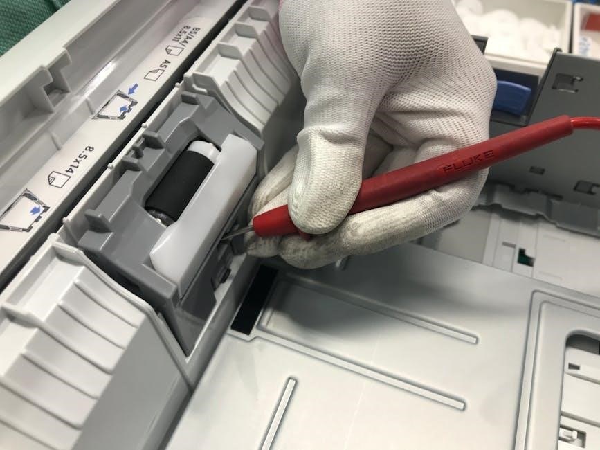
When troubleshooting CDI electronics, always wear protective gear like gloves and goggles. Ensure the ignition system is grounded to prevent accidental sparks. Essential tools include a multimeter, voltage adapter, and jumper wires. Avoid using damaged tools, as they can compromise safety and accuracy. Refer to the CDI Electronics website for recommended tools and safety guidelines to ensure proper diagnostics and repairs.
1.2 Importance of Troubleshooting Guides and Manuals
Troubleshooting guides and manuals are crucial for efficiently diagnosing and repairing CDI electronics. They provide detailed diagrams, specifications, and step-by-step procedures, ensuring accurate repairs. These resources help technicians identify issues quickly, reducing downtime and costs. Always refer to official CDI Electronics manuals for precise information tailored to specific systems, ensuring safety and optimal performance.
Understanding CDI Ignition Wiring
CDI ignition wiring is structured to ensure proper spark generation. It includes key components like the kill circuit and ignition switch, which must be tested for optimal performance.
2.1 Identifying Key Components and Their Functions
The CDI ignition system comprises essential components, including the ignition coil, stator, and trigger wires. Each part plays a critical role in generating and delivering the spark. The ignition coil amplifies voltage, while the stator produces energy. Trigger wires synchronize the firing sequence, ensuring precise spark delivery. Proper function of these components is vital for reliable engine operation and performance.
2.2 Common Issues in Ignition Wiring and Solutions
Common issues in ignition wiring include corrosion in connectors, chafed wires, and voltage drops. Solutions involve inspecting wires for damage, using multimeters to test resistance, and ensuring proper connections. Replacing faulty components and avoiding ground faults can prevent spark loss and maintain system reliability.

Diagnosing No Spark or Intermittent Spark Issues
Diagnosing no spark or intermittent spark involves checking the kill circuit, ignition switch, and DVA output. Ensure all connections are secure and test stator resistance for faults.
3.1 Checking the Kill Circuit and Ignition Switch
To diagnose no spark issues, start by inspecting the kill circuit. Disconnect the kill wire at the CDI unit and check for continuity. If the issue persists, test the ignition switch’s Red/Yellow wire for 12V when the key is on. Use a multimeter to verify connections and ensure no shorts or breaks in the wiring harness. A faulty kill switch or ignition switch can prevent spark generation entirely.
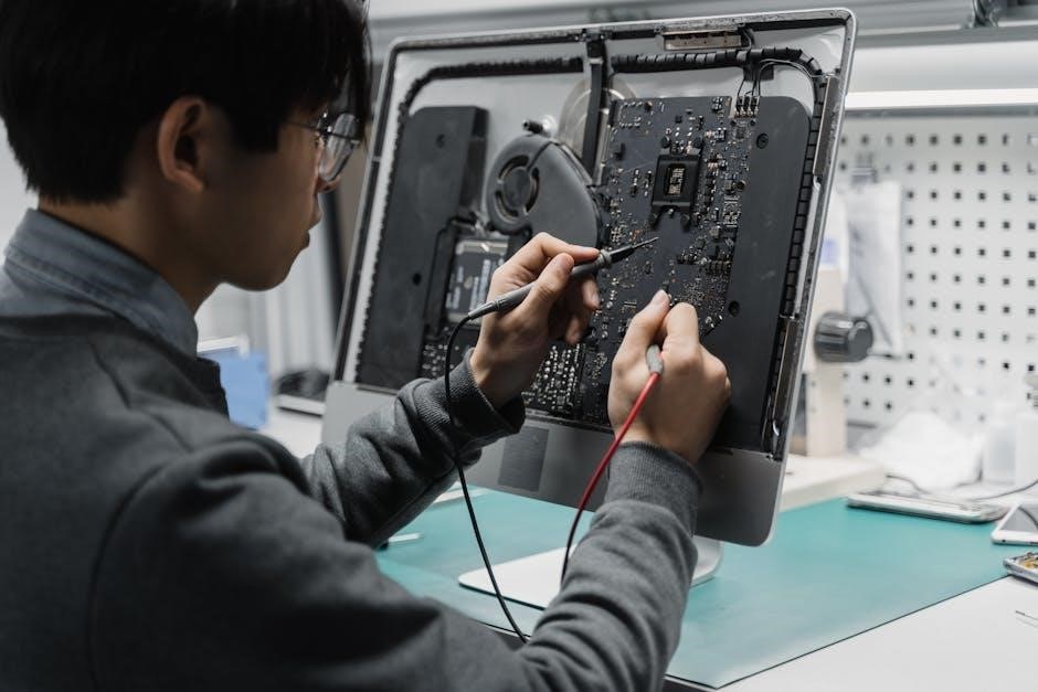
3.2 Measuring DVA Output and Stator Resistance
Measure the DVA output by connecting a multimeter to the Green and Green/White wires from the stator. Use a DVA adapter for accurate readings. Compare the results to the manufacturer’s specifications. Next, check the stator resistance using the ohms function on your multimeter. Ensure the readings align with the recommended values to confirm the stator’s functionality and rule out internal faults.

Troubleshooting the Kill Circuit
To troubleshoot the kill circuit, use a multimeter to test the kill switch and wiring harness for continuity and shorts. Utilize jumper wires to identify circuit faults and ensure proper grounding.
4.1 Testing the Kill Switch and Wiring Harness
Start by testing the kill switch for continuity using a multimeter. Check for any shorts or open circuits in the wiring harness. Ensure proper grounding and inspect for damaged or corroded connections. Use jumper wires to bypass suspect components, verifying if the kill circuit functions correctly. This step-by-step approach helps isolate faults efficiently.
4.2 Using Jumper Wires to Identify Circuit Faults
Using jumper wires is a reliable method to bypass suspect components and isolate faults in the kill circuit. Connect a jumper wire to the black/yellow terminal and ground it to test functionality. This technique helps determine if the issue lies within the wiring or the switch itself, streamlining the troubleshooting process effectively.

Voltage Drop Measurement Techniques
Voltage drop tests are crucial for identifying circuit faults in CDI systems. Use a multimeter to measure voltage across components, ensuring connections are secure and functioning properly.
5.1 Understanding Voltage Drop in CDI Systems
Voltage drop in CDI systems occurs when electrical current encounters resistance, leading to reduced voltage at components; This can cause ignition issues, such as no spark or intermittent spark. Identifying excessive drops helps pinpoint faulty wiring, connectors, or components. Proper testing ensures accurate diagnosis and effective repairs, maintaining system performance and reliability.
5.2 Step-by-Step Voltage Drop Testing Procedure
- Set your multimeter to DC voltage and connect it in parallel across the circuit.
- Measure voltage drop at key points, including the battery, ignition switch, and CDI unit.
- Check for drops exceeding 0.5V, indicating potential issues in wiring or connections.
- Inspect wires and connectors for damage or corrosion that may cause resistance.
- Repeat tests under load to identify intermittent faults.
Advanced CDI Troubleshooting Methods
Advanced CDI troubleshooting involves using specialized tools like oscilloscopes to analyze spark patterns and measure DVA outputs accurately. These techniques help identify complex issues quickly and efficiently.

6.1 Using Oscilloscopes for Spark Analysis
An oscilloscope is a powerful tool for analyzing spark patterns in CDI systems. By connecting it to the ignition coil or DVA output, technicians can visualize waveform shapes and identify irregularities. This helps diagnose issues like intermittent sparks or faulty components accurately.
Using a CDI-specific oscilloscope adapter ensures precise measurements. This method allows technicians to pinpoint electrical fluctuations, confirming whether the spark output meets manufacturer specifications. It’s an advanced technique for resolving complex ignition problems effectively without guesswork.
6.2 Checking Flywheel Timing and Trigger Wires
Accurate flywheel timing is crucial for proper spark generation. Misalignment or wear in the trigger wires can disrupt the ignition signal, causing intermittent or no spark issues. Technicians should index the flywheel and inspect the trigger wires for damage or poor connections. Consulting the service manual for specific timing specifications ensures precise adjustments and reliable engine performance;
If the timing is off, swapping trigger wires or replacing faulty components may resolve the issue. Regular maintenance of these components prevents common ignition-related problems and ensures optimal CDI system functionality.
Common CDI-Related Problems and Solutions
Common issues include no spark, intermittent spark, or misfires. These often stem from faulty wiring, failed components, or incorrect timing. Systematic troubleshooting using multimeters and manuals helps identify root causes, ensuring accurate repairs and optimal ignition performance.
7.1 No Spark on All Cylinders: Possible Causes
No spark on all cylinders can result from issues like a faulty kill circuit, failed ignition switch, or broken wiring. Low DVA output, high stator resistance, or a malfunctioning CDI unit are common causes. Additionally, incorrect flywheel timing or damaged trigger wires can disrupt the ignition process, leading to a complete loss of spark across all cylinders.
7.2 Intermittent Spark on One Cylinder: Diagnostic Steps
For intermittent spark on one cylinder, inspect the kill circuit and ignition switch. Check the DVA output between specific wires and measure stator resistance. Verify connections at the CDI unit and key switch. Ensure trigger wires are secure and not damaged. Faulty components like the ignition coil or spark plug wire may also cause this issue, requiring replacement if defective.
Essential Marine Shop Electrical Test Equipment
A digital multimeter, DVA adapter, and oscilloscope are crucial for diagnosing CDI systems. These tools enable precise voltage, resistance, and spark pattern measurements, ensuring accurate troubleshooting.
8.1 Recommended Multimeters and Adapters
A digital multimeter is essential for measuring voltage, resistance, and continuity in CDI systems. The CDI DVA adapter simplifies testing of electronic ignition systems and works with shielded multimeters for accurate readings. These tools are critical for diagnosing issues like no spark or intermittent spark by measuring DVA output and stator resistance effectively.
8.2 Tricks for Testing with Minimal Tools
When advanced tools are unavailable, use jumper wires to bypass circuits and isolate faults. Check connections and wiring for damage or corrosion. Measure resistance and voltage drop using a basic multimeter. These techniques help identify issues like faulty kill circuits or ignition switches without specialized equipment, ensuring effective troubleshooting even with limited resources.

CDI Electronics Installation and Maintenance Tips
Proper installation ensures secure connections and correct wiring. Regular maintenance involves inspecting wires, cleaning connections, and tightening components to prevent faults and ensure reliable performance.
9.1 Proper Installation Procedures for CDI Units
Ensure the battery is disconnected before starting. Mount the CDI unit securely, away from heat sources. Connect wires according to the diagram, verifying polarity. Test DVA output with a multimeter. Check all connections for tightness and insulation. Finally, reconnect the battery and test the system to confirm proper operation and spark generation.
9.2 Regular Maintenance to Prevent Common Issues
Inspect wiring for damage or corrosion and clean all connections. Check the kill circuit and stator for proper function. Perform benchmark testing of DVA output and resistance. Regularly verify the flywheel timing and trigger alignment. Keep the system free from moisture and debris. These steps ensure reliable operation and prevent common ignition-related problems.
For further assistance, refer to CDI Electronics for comprehensive guides, manuals, and technical support. Their resources provide detailed troubleshooting steps and advanced diagnostic techniques.
10.1 Summary of Key Troubleshooting Steps
Effective troubleshooting involves checking the kill circuit, measuring DVA output, and testing voltage drops. Always consult CDI manuals for specific guidance. Use multimeters and oscilloscopes for precise diagnostics. Verify connections and wiring integrity, and ensure proper installation of components. Regular maintenance and understanding ignition wiring are crucial for preventing and resolving issues efficiently.
10.2 Where to Find Additional Support and Manuals
For comprehensive resources, visit the official CDI Electronics website. They offer detailed troubleshooting guides, repair manuals, and technical support. The CDI Electronics Troubleshooting Guide (6th Edition) is particularly useful for advanced diagnostics. Contact their technical support team at 1.866.423.4832 for personalized assistance. Additional materials, including instructional videos, are available to help resolve complex ignition issues effectively.